TCC-45 LTLP installation instructions for existing weld-on or cast-in "low profile" block style side bearing pockets.
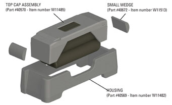
Included in each assembly are:
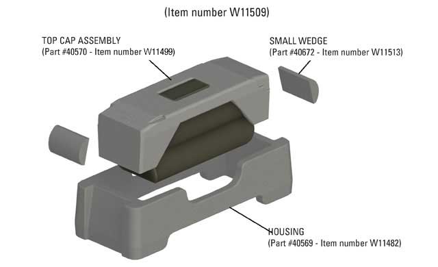
• one metal top cap attached to a TecsPak® spring
• one housing
• two small wedges
Specifications:
• installed height of 2-5/8 in. (66 mm)
• 4,500 lbs. of preload
• 5/8 in. (16 mm) of travel
STEP 1 - PREPARATION
STEP 2 - SET-UP HEIGHT ADJUSTMENT
STEP 3 - HOUSING SECUREMENT
STEP 4 - SHIMMING
STEP 5 - WELDING INSTRUCTIONS
STEP 6 - FINAL ASSEMBLY
STEP 1 - PREPARATION
– Remove the metal block and clean the pocket of any foreign material.
– Inspect the pocket for cracks or any other damage, and repair if necessary.
– Ensure that the pocket bottom and end walls are relatively smooth and free of any weld spatter, bumps, etc.
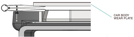
Car Body Wear Plate
– Must be large enough based upon the car truck centers reference table below.
– The car body side bearing wear plate surface must be smooth. Any weld spatter, heavy rust or surface projections must be removed by grinding.
– Fastener heads must be smooth and not protruding below wear plate surface, and the fasteners securely tightened.
– Plates with surface variations between fastener holes greater than 1/8 in. (3 mm), or greater than 1/16 in. (1 mm) over any 4 in. (101 mm) space between the fastener holes, must be replaced.
– Surface must be reasonably parallel to side bearing mounting surface. Variations should not exceed 1/16 in. (1 mm) across width or 1/8 in. (3 mm) end to end.
Car Body Wear Plate Reference |
||
Truck Centers |
Min. Width |
Min. Length |
70 ft. (21 m) or less |
4 in. (101 mm) |
12 in. (305 mm) |
70+ ft. (21 m) to 82 ft. (25 m) |
4 in. (101 mm) |
14 in. (356 mm) |
82+ ft. (25 m) to 94 ft. (29 m) |
4 in. (101 mm) |
16 in. (406 mm) |
Greater than 94 ft. (29 m) |
4 in. (101 mm) |
18 in. (458 mm) |
Please refer to AAR Manual Rule 61 for more detailed info regarding body wear plates |
||
STEP 2 - SET-UP HEIGHT ADJUSTMENT
1. The TCC-45 LTLP housing is 2 in. (51 mm) tall and acts as the solid stop. Therefore, the housing must extend above the pocket wall around the entire perimeter, up to a maximum of 3/8 in. (9 mm).
2. If the pocket wall is taller than the housing, either:
a. add steel shims under the bottom of the housing covering the entire pocket floor
b. remove enough material from the top of wall to ensure the housing is above the pocket wall with a max of 3/8 in. (9 mm) extension
3. The set-up height should be adjusted by measuring between the top of the housing and the underside of the car-body wear plate with an empty car positioned on level track before installing the top cap assembly or applying solid center plate lube.
4. Adjust shims as necessary to achieve 5/8 in. (16 mm) +/- 1/16 in. (1 mm)
5. Car body wear plate must be large enough (see above)
STEP 3 - HOUSING SECUREMENT
Determine Pocket Size – There are many different sizes of pockets that are currently in service. Larger pockets (see below dimensions) will require a different model.
Use the TCC-45 LTLP-B for pockets equal to or larger than 9-¼ in. (235 mm) x 4-¼ in. (108 mm).
NOTE: use the small wedges to install the TCC-45 LTLP into the following pocket dimensions.
Min Inside Length = 8-1/8 in. (206 mm)
Max Inside Length = 8-11/16 in. (221 mm)
Min Inside Width = 3-1/4 in. (83 mm)
Shimming is required if pocket length is greater than 8-11/16 in. (221 mm). See Pocket Adjustment Instructions below.
- Shift the housing in the pocket to the outboard side of the bolster.
- Insert wedges in both ends.
- Ensure that the flat side of the wedge is against the Miner housing and rounded side is against the pocket wall.
- Ensure that the wedges do not extend beyond the housing top surface.
- Once the welds are finished and cool, insert the top cap assembly with the metal cap facing upwards and lower the car body.
STEP 4 - SHIMMING
![]()
Shims are required for the following pocket dimensions:
Inside Length Greater than 8-11/16 in. (221 mm)
Optimal inside length after shimming should be 8-1/4 in (210 mm).
Shims to be of mild, weldable steel material.
Inside Length - If the wedges hit the pocket floor before contacting the end wall (inside length roughly greater than 8-11/16 in. (221 mm), shim application is required.
1. Ensure shim is thick enough to keep wedge off pocket floor.
2. Fabricate the shim so that it is ¼ in. (6 mm) shorter than the pocket wall and no wider than the flat portion of the end wall. Leave enough room on the shim width for welding. See welding instructions.
Inside Width - If there is a gap greater than 1/4 in. (6 mm), shimming will be required.
1. Estimate the shim thickness needed to reduce the pocket width to between 3 1/8 in. (79 mm) and 3 3/8 in. (86 mm).
2. Fabricate the shim so that it is approximately ¼ in. (6 mm) shorter than the pocket wall and no longer than the flat portion of the pocket side wall. Leave enough room on the shim length for welding. See welding instructions.
STEP 5 - WELDING INSTRUCTIONS
Remove the top cap assembly from housing prior to welding.
Warning: Do not weld near the top cap assembly.
Warning: Do not weld directly to either Miner housing or top cap.
All surface preparation and welding must comply with AWS D15.1 Railroad Welding Specification – Cars and Locomotives, latest edition. Specification M-214 can be used for more information on preheating.
1. Grind, clean and prepare for welding.
2. For cast pockets, AAR M-214 recommends preheating between 300° F (149° C) and 600° F (315° C), not exceeding 600° F (315° C).
3. Materials
• Type of weld: Flare bevel groove
• Wedge: Cast Steel ASTM-A-27 Grade 65-35
• For cast in pockets determine Grade of Steel of the bolster casting: Reference AAR Standard S-312
– Grade B bolsters use AWS electrode E7018, or equivalent
– Grade B+ bolsters use AWS electrode E8018, or equivalent
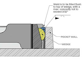
– Grade C bolsters use AWS electrode E9018, or equivalent• For fabricated pocket, identify material and choose appropriate electrode per AWS D15.1 If the wedge is below the pocket wall, add reinforcement fillet weld on top. See wedge welding cutaway illustration.
STEP 6 - FINAL ASSEMBLY
1. After the weld has cooled, place top cap assembly into housing and lower car.
2. The TecsPak® pad must not be exposed to temperature environments higher than 200˚ F (93˚ C) or 175˚ F (79˚ C) for extended periods of time (2-3 hours).
3. After the side bearings have been installed, and the car body lowered onto the trucks, the set up height will probably be greater than the original set up.
4. Initial set needs to take place and this height will gradually reach the design set-up height.
5. The TecsPak® pads should be maintained at a 40° F (4˚ C) or higher temperature for at least 24 hours before assembly on a car.
6. At temperatures lower than 40° F (4˚ C), the settling time for the setup height may require at least 24 hours.
TCC-45 LTLP installation instructions for existing weld-on or cast-in "low profile" block style side bearing pockets.
Included in each assembly are:
• one metal top cap attached to a TecsPak® spring
• one housing
• two small wedges
Specifications:
• installed height of 2-5/8 in. (66 mm)
• 4,500 lbs. of preload
• 5/8 in. (16 mm) of travel
STEP 1 - PREPARATION
STEP 2 - SET-UP HEIGHT ADJUSTMENT
STEP 3 - HOUSING SECUREMENT
STEP 4 - SHIMMING
STEP 5 - WELDING INSTRUCTIONS
STEP 6 - FINAL ASSEMBLY
STEP 1 - PREPARATION
– Remove the metal block and clean the pocket of any foreign material.
– Inspect the pocket for cracks or any other damage, and repair if necessary.
– Ensure that the pocket bottom and end walls are relatively smooth and free of any weld spatter, bumps, etc.
Car Body Wear Plate
– Must be large enough based upon the car truck centers reference table below.
– The car body side bearing wear plate surface must be smooth. Any weld spatter, heavy rust or surface projections must be removed by grinding.
– Fastener heads must be smooth and not protruding below wear plate surface, and the fasteners securely tightened.
– Plates with surface variations between fastener holes greater than 1/8 in. (3 mm), or greater than 1/16 in. (1 mm) over any 4 in. (101 mm) space between the fastener holes, must be replaced.
– Surface must be reasonably parallel to side bearing mounting surface. Variations should not exceed 1/16 in. (1 mm) across width or 1/8 in. (3 mm) end to end.
Car Body Wear Plate Reference |
||
Truck Centers |
Min. Width |
Min. Length |
70 ft. (21 m) or less |
4 in. (101 mm) |
12 in. (305 mm) |
70+ ft. (21 m) to 82 ft. (25 m) |
4 in. (101 mm) |
14 in. (356 mm) |
82+ ft. (25 m) to 94 ft. (29 m) |
4 in. (101 mm) |
16 in. (406 mm) |
Greater than 94 ft. (29 m) |
4 in. (101 mm) |
18 in. (458 mm) |
Please refer to AAR Manual Rule 61 for more detailed info regarding body wear plates |
||
STEP 2 - SET-UP HEIGHT ADJUSTMENT
1. The TCC-45 LTLP housing is 2 in. (51 mm) tall and acts as the solid stop. Therefore, the housing must extend above the pocket wall around the entire perimeter, up to a maximum of 3/8 in. (9 mm).
2. If the steel pocket wall is taller than the housing, either:
a. add shims under the bottom of the housing covering the entire pocket floor
b. remove enough material from the top of wall to ensure the housing is above the pocket wall with a max of 3/8 in. (9 mm) extension
3. The set-up height should be adjusted by measuring between the top of the housing and the underside of the car-body wear plate with an empty car positioned on level track before installing the top cap assembly or applying solid center plate lube.
4. Adjust shims as necessary to achieve 5/8 in. (16 mm) +/- 1/16 in. (1 mm)
5. Car body wear plate must be large enough (see above)
STEP 3 - HOUSING SECUREMENT
Determine Pocket Size – There are many different sizes of pockets that are currently in service. Larger pockets (see below dimensions) will require a different model.
Use the TCC-45 LTLP-B for pockets equal to or larger than 9-¼ in. (235 mm) x 4-¼ in. (108 mm).
NOTE: use the small wedges to install the TCC-45 LTLP into the following pocket dimensions.
Min Inside Length = 8-1/8 in. (206 mm)
Max Inside Length = 8-11/16 in. (221 mm)
Min Inside Width = 3-1/4 in. (83 mm)
Shimming is required if pocket length is greater than 8-11/16 in. (221 mm). See Pocket Adjustment Instructions below.
- Shift the housing in the pocket to the outboard side of the bolster.
- Insert wedges in both ends.
- Ensure that the flat side of the wedge is against the Miner housing and rounded side is against the pocket wall.
- Ensure that the wedges do not extend beyond the housing top surface.
- Once the welds are finished and cool, insert the top cap assembly with the metal cap facing upwards and lower the car body.
STEP 4 - SHIMMING
![]()
Shims are required for the following pocket dimensions:
Inside Length Greater than 8-11/16 in. (221 mm)
Optimal inside length after shimming should be 8-1/4 in (210 mm).
Shims to be of mild, weldable steel material.
Inside Length - If the wedges hit the pocket floor before contacting the end wall (inside length roughly greater than 8-11/16 in. (221 mm), shim application is required.
1. Ensure shim is thick enough to keep wedge off pocket floor.
2. Fabricate the shim so that it is ¼ in. (6 mm) shorter than the pocket wall and no wider than the flat portion of the end wall. Leave enough room on the shim width for welding. See welding instructions.
Inside Width - If there is a gap greater than 1/4 in. (6 mm), shimming will be required.
1. Estimate the shim thickness needed to reduce the pocket width to between 3 1/8 in. (79 mm) and 3 3/8 in. (86 mm).
2. Fabricate the shim so that it is approximately ¼ in. (6 mm) shorter than the pocket wall and no longer than the flat portion of the pocket side wall. Leave enough room on the shim length for welding. See welding instructions.
STEP 5 - WELDING INSTRUCTIONS
Remove the top cap assembly from housing prior to welding.
Warning: Do not weld near the top cap assembly.
Warning: Do not weld directly to either Miner housing or top cap.
All surface preparation and welding must comply with AWS D15.1 Railroad Welding Specification – Cars and Locomotives, latest edition. Specification M-214 can be used for more information on preheating.
1. Grind, clean and prepare for welding.
2. For cast pockets, AAR M-214 recommends preheating between 300° F (149° C) and 600° F (315° C), not exceeding 600° F (315° C).
3. Materials
• Type of weld: Flare bevel groove
• Wedge: Cast Steel ASTM-A-27 Grade 65-35
• For cast in pockets determine Grade of Steel of the bolster casting: Reference AAR Standard S-312
– Grade B bolsters use AWS electrode E7018, or equivalent
– Grade B+ bolsters use AWS electrode E8018, or equivalent
– Grade C bolsters use AWS electrode E9018, or equivalent• For fabricated pocket, identify material and choose appropriate electrode per AWS D15.1 If the wedge is below the pocket wall, add reinforcement fillet weld on top. See wedge welding cutaway illustration.
STEP 6 - FINAL ASSEMBLY
1. After the weld has cooled, place top cap assembly into housing and lower car.
2. The TecsPak® pad must not be exposed to temperature environments higher than 200˚ F (93˚ C) or 175˚ F (79˚ C) for extended periods of time (2-3 hours).
3. After the side bearings have been installed, and the car body lowered onto the trucks, the set up height will probably be greater than the original set up.
4. Initial set needs to take place and this height will gradually reach the design set-up height.
5. The TecsPak® pads should be maintained at a 40° F (4˚ C) or higher temperature for at least 24 hours before assembly on a car.
6. At temperatures lower than 40° F (4˚ C), the settling time for the setup height may require at least 24 hours.
Reference images below. Choose a TCC-45 LTLP install option from the buttons below.