TCC-45 LTLP-C installation instructions for existing "low profile" bolt-on applications.
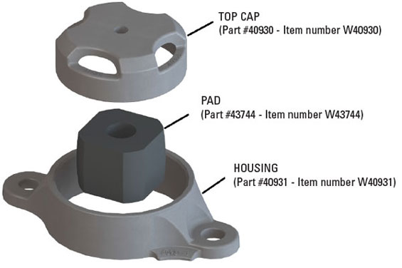
Included in each assembly are:
– one metal top cap
– one TecsPak® spring
– one bolt-on housing
Specifications:
– installed height of 2-5/8 in. (66 mm)
– 4,500 lbs. of preload
– 5/8 in. (16 mm) of travel
STEP 1 - PREPARATION
STEP 2 - SET-UP HEIGHT ADJUSTMENT
STEP 3 - HOUSING SECUREMENT
STEP 4 - FINAL ASSEMBLY
STEP 1 - PREPARATION
Pocket / Mounting Surface
- Remove the metal block and clean the pocket of any foreign material.
- Inspect the pocket for cracks or any other damage, and repair if necessary.
- Ensure that the pocket bottom and end walls are relatively smooth and free of any weld spatter, bumps, etc.
- Clean the mounting surface for bolt-on application.
Car Body Wear Plate
- The car body side bearing wear plate surface must be smooth. Any weld spatter, heavy rust or surface projections must be removed by grinding.
- Fastener heads must be smooth and not protruding below wear plate surface, and the fasteners securely tightened.
- Plates with surface variations between fastener holes greater than 1/8 in. (3 mm), or greater than 1/16 in. (1 mm) over any 4 in. (101 mm) space between the fastener holes, must be replaced.
- Surface must be reasonably parallel to side bearing mounting surface. Variations should not exceed 1/16 in. (1 mm) across width or 1/8 in. (3 mm) end to end.
Truck Centers |
Min. Width |
Min. Length |
70 ft. (21 m) or less |
4 in. (101 mm) |
12 in. (305 mm) |
70+ ft. (21 m) to 82 ft. (25 m) |
4 in. (101 mm) |
14 in. (356 mm) |
82+ ft. (25 m) to 94 ft. (29 m) |
4 in. (101 mm) |
16 in. (406 mm) |
Greater than 94 ft. (29 m) |
4 in. (101 mm) |
18 in. (458 mm) |
Please refer to AAR Manual Rule 61 for more detailed info regarding body wear plates |
||
STEP 2 - SET-UP HEIGHT ADJUSTMENT
- The LTLP-C housing is 2 in. (51 mm) tall and acts as the solid stop.
- The set-up height should be adjusted by measuring between the top of the housing and the underside of the car-body wear plate with an empty car positioned on level track before installing the top cap assembly or applying solid center plate lube.
- Car body wear plate must be large enough (see above).
STEP 3 - HOUSING SECUREMENT
Bolt-on application
- Surface must be clean and smooth and free of protrusions. Reference AAR standards:
- S-3013 Side Bearing Mounting Pad - Surface Requirements
- S-394 Side Bearing Pad for Two Hole Application
- AAR bolt hole location is 8-1/2 in. (216 mm).
- Bolt housing to bolster using appropriate fasteners and torque requirements.
Acceptable fasteners:
- Camcar standard dome head fastener (reference part #794-20100-130)
- Huck fastener (reference part #C71LR-BR24-28/32 and #3LC-2R24GL).
- 7/8"-9 Grade 5 or better HEX head bolt with self-locking nut.
Torque:
- Dry: 375-425 ft.-lbs. (Produces a clamping force of 20,000-30,000 lbs. per bolt).
- Waxed or well lubricated threads: 280-320 ft.-lbs. (Roughly 25% reduction from dry values).
STEP 4 - FINAL ASSEMBLY
1. Place TecsPak® pad inside the housing.
2. Place top cap on pad. There is a male end on top cap that should go inside the female end of the pad.
TCC-45 LTLP-C installation instructions for existing "low profile" bolt-on applications.
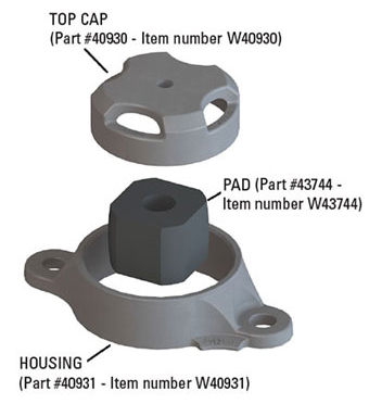
Included in each assembly are:
– one metal top cap
– one TecsPak® spring
– one bolt-on housing
Specifications:
– installed height of 2-5/8 in. (66 mm)
– 4,500 lbs. of preload
– 5/8 in. (16 mm) of travel
STEP 1 - PREPARATION
STEP 2 - SET-UP HEIGHT ADJUSTMENT
STEP 3 - HOUSING SECUREMENT
STEP 4 - FINAL ASSEMBLY
STEP 1 - PREPARATION
Pocket / Mounting Surface
- Remove the metal block and clean the pocket of any foreign material.
- Inspect the pocket for cracks or any other damage, and repair if necessary.
- Ensure that the pocket bottom and end walls are relatively smooth and free of any weld spatter, bumps, etc.
- Clean the mounting surface for bolt-on application.
Car Body Wear Plate
- The car body side bearing wear plate surface must be smooth. Any weld spatter, heavy rust or surface projections must be removed by grinding.
- Fastener heads must be smooth and not protruding below wear plate surface, and the fasteners securely tightened.
- Plates with surface variations between fastener holes greater than 1/8 in. (3 mm), or greater than 1/16 in. (1 mm) over any 4 in. (101 mm) space between the fastener holes, must be replaced.
- Surface must be reasonably parallel to side bearing mounting surface. Variations should not exceed 1/16 in. (1 mm) across width or 1/8 in. (3 mm) end to end.
Truck Centers |
Min. Width |
Min. Length |
70 ft. (21 m) or less |
4 in. (101 mm) |
12 in. (305 mm) |
70+ ft. (21 m) to 82 ft. (25 m) |
4 in. (101 mm) |
14 in. (356 mm) |
82+ ft. (25 m) to 94 ft. (29 m) |
4 in. (101 mm) |
16 in. (406 mm) |
Greater than 94 ft. (29 m) |
4 in. (101 mm) |
18 in. (458 mm) |
Please refer to AAR Manual Rule 61 for more detailed info regarding body wear plates |
||
STEP 2 - SET-UP HEIGHT ADJUSTMENT
- The LTLP-C housing is 2 in. (51 mm) tall and acts as the solid stop.
- The set-up height should be adjusted by measuring between the top of the housing and the underside of the car-body wear plate with an empty car positioned on level track before installing the top cap assembly or applying solid center plate lube.
- Car body wear plate must be large enough (see above).
STEP 3 - HOUSING SECUREMENT
Bolt-on application
- Surface must be clean and smooth and free of protrusions. Reference AAR standards:
- S-3013 Side Bearing Mounting Pad - Surface Requirements
- S-394 Side Bearing Pad for Two Hole Application
- AAR bolt hole location is 8-1/2 in. (216 mm).
- Bolt housing to bolster using appropriate fasteners and torque requirements.
Acceptable fasteners:
- Camcar standard dome head fastener (reference part #794-20100-130)
- Huck fastener (reference part #C71LR-BR24-28/32 and #3LC-2R24GL).
- 7/8"-9 Grade 5 or better HEX head bolt with self-locking nut.
Torque:
- Dry: 375-425 ft.-lbs. (Produces a clamping force of 20,000-30,000 lbs. per bolt).
- Waxed or well lubricated threads: 280-320 ft.-lbs. (Roughly 25% reduction from dry values).
STEP 4 - FINAL ASSEMBLY
1. Place TecsPak® pad inside the housing.
2. Place top cap on pad. There is a male end on top cap that should go inside the female end of the pad.